Weather Model (HARMONIE)
Description
DMI uses and codevelops the weather model HARMONIE. The weather model produces forecast data for e.g. temperature, dew point temperature, cloud cover, wind, pressure and several others parameters. DMI’s weather model HARMONIE covers the geographical area Northwestern Europe (NEA). ´he weather model uses a grid resolution of 2.5 km. DMI’s HARMONIE model runs cycle 43 for NEA (https://journals.ametsoc.org/view/journals/mwre/145/5/mwr-d-16-0417.1.xml (external site)) with boundary conditions from the global weather model ECMWF.
The model focuses on events that take place on small scale but can have serious outcomes, e.g. extreme precipitation like cloudburst (convective precipitation) and rapidly changing storm low.
HARMONIE is an abbreviation of Hirlam Aladin Research towards Mesoscale Operational NWP in Europe and is developed through an international collaboration. Hirlam and Aladin are the names of two groups of meteorological institutions in Europe, therefore HARMONIE has a broad European foundation.
DMI’s HARMONIE model also creates start input for DMI’s downstream ocean models (Wave Model WAM and Storm Surge model DKSS).
Number of Runs and Forecast Range
DMI’s HARMONIE model runs every hour on our supercomputer located in Iceland. DMI only collects the deterministic run every third hour (00z, 03z, 06z, 09z, 12z, 15z, 18z and 21z). Every run produces a forecast of the atmospheres 3-dimensional condition for the next days.
The forecast range for HARMONIE varies based on what time the model run begins. In the table below, you can see the forecast range for the different model run times:
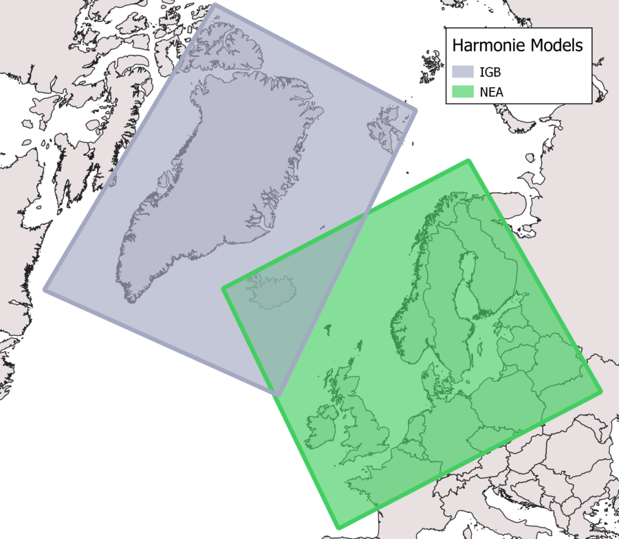
Model areas
HARMONIE has one geographical area: NEA that covers Northwestern Europe. IGB has been replaced with the IG model.
Types of model output:
The weather model has three types of model output:
- Surface (sf)
- Model levels (ml)
- Pressure levels (pl)
Surface levels (sf)
The surface files consist of a combination of the model’s surface scheme and interpolation from the model layers. The surface files therefore consists of parameters that are defined by the surface (e.g. soil temperature, 2 m temperature, 10 m wind). The surface files also contain parameters that are integrated across layers through the entire atmosphere (e.g. precipitation and cloud cover). It is in the surface level files, that you will find the most common parameters.
Please also see the parameter list.
Model levels (ml)
The first raw output data from the model are model levels. NEA has 65 layers that all describe the atmosphere. The layers are placed close together at the surface and gradually move further apart up through the atmosphere. Close by the earth’s surface the layers follow the surface’s topography. Further up in the atmosphere the layers follow the pressure levels.
Please also see the parameter list.
Pressure levels (pl)
The model levels are recalculated to relevant pressure levels (see pressure levels below) and selected parameters are interpolated to these pressure levels.
The pressure levels are: 1000, 950, 925, 900, 850, 800, 700, 600, 500, 400, 300, 250, 200, 150, 100, and 50hPa.
The calculated parameters are: vertical speed, wind components u and v, temperature, geopotential, relative humidity, geometrical vertical speed, pseudoadiabatic potential temperature, potential vorticity.
Please also see the parameter list.
Rotated coordinate system
The data in the HARMONIE grib files are given in rotated latitude and longitude coordinates in order to minimize the files size. Therefore the coordinates in the grib files have to be rotated correctly before they can be used. If this is not done, the coordinates are not correct (located in a grid around the equator and prime meridian ie. lat/lon 0,0.)
E.g., the extends in the grib file HARMONIE_NEA is -22.761,-0.631 : 3.397,22.887, which should be -28.620508,44.3829 : 37.007052,72.876.
Some programs like GDAL based tools (QGIS for example) understand this rotation and can do this automatically. Some tools do not.
Rotation
DMI's HARMONIE model uses a rotated pole coordinate reference system. For the NEA model (North East Atlantic, ie. Denmark) its south pole is at 26.5°,-40°.
All coordinates in the HARMONIE model are defined in these coordinate systems. In order to convert the coordinates to a "regular" coordinate system (something using the equator as 0 parallel and prime meridian as 0 meridian e.g. WGS84), you have to rotate the earth sphere on which the coordinate sits. You perform the same rotation the south pole of the coordinate system has gone through, so in the case of the NEA model you would rotate 50 degrees north (from -90° to -40°) and 26.5 degrees east (from 0° to 26.5°). The reverse process is applicable if you have coordinate that you need to find in the model coordinate system.
Conversion by rotation is easier said than done, so DMI recommends using either the PROJ projection software (see PROJ section below) or copying/translating the provided code below (see "Using Code" section below).
If you are using wind data, be advised that wind direction is defined in its native rotated pole coordinate reference system, and must also be rotated if you transform the coordinates into a geodetic coordinate system (ie. latitude/longitude). For more on this, see the "Rotating parameter values" section.
Explanation of HARMONIE's rotated pole CRS
A rotated pole coordinate system is a latitude/longitude grid that is rotated so its south pole aligns with a given coordinate. As an example, the south pole of HARMONIE NEA must be rotated to longitude 26.5° and latitude -40°. The animation below illustrates how this rotation works. The end result is the coordinate system of the coordinates in the HARMONIE NEA model. This is where rotated pole gets its name from.

In the animation the black lines are reference latitude/longitude lines. The red points are sample points in the HARMONIE model, and of course stay the same in physical space regardless of which coordinate system is used. The yellow point is where the south pole of the coordinate system must be rotated to.
A cylindrical map projection of this new coordinate system with its new 0 parallel and meridian (ie. an oblique mercator projection) yields a map like this:
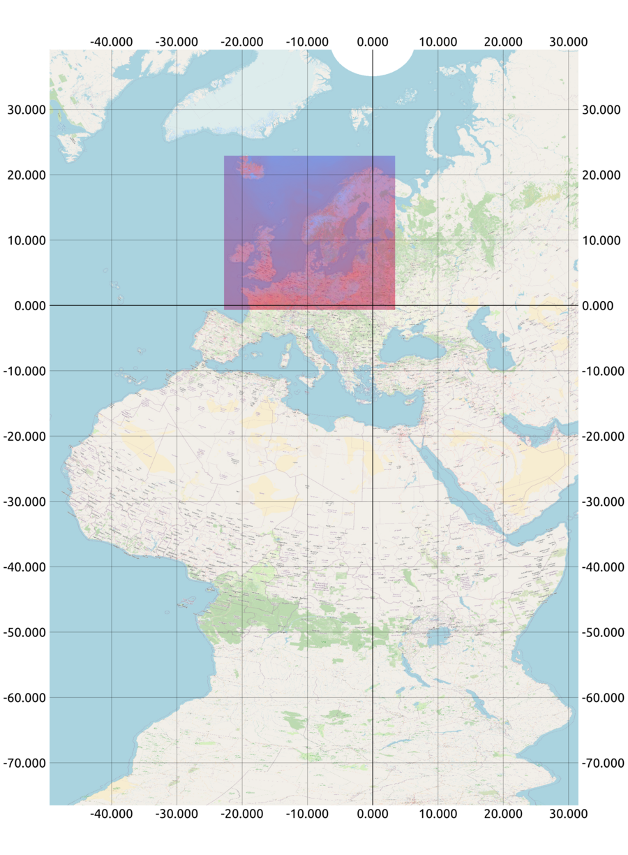
Notice how the HARMONIE NEA model area (ie. the blue/red square showing temperature) is perfectly square. The underlying coordinates for the data points are in a grid, where all rows share latitude, and all columns share longitude. Having the coordinates in a grid structure makes model data easier to work with.
There are great advantages in using this coordinate system, and the main ones are:
The coordinate system locates the HARMONIE model domain close to the 0 parallel (ie. its "new" equator), so the deviation of distance and area is relatively low in the model domain. If you find the deviation negligible, the coordinate system can be treated as a Cartesian coordinate system.
The coordinate system gives the model domain nice local coordinates, ie. coordinates are situated around the coordinate (0,0)
When combined with an oblique mercator projection like the one shown above, a map of weather phenomenons will pretty accurately show features like shape, distance and area within the model area.
Rotating coordinates
Using the PROJ projection software
PROJ (external site) is a generic coordinate transformation software that transforms geospatial coordinates from one coordinate reference system (CRS) to another.
The coordinate reference system used by either HARMONIE model is not in the public EPSG registry, meaning it's a non-standard coordinate reference system. Therefore, this custom proj-string (external site) must be used to transform coordinates to a geodetic coordinate system (ie. latitude/longitude).
For HARMONIE NEA the proj string is:
| +proj=ob_tran +o_proj=longlat +o_lon_p=0 +o_lat_p=40 +lon_0=26.5 +R=6367470 +no_defs |
The proj-string describes an oblique transformation (external site). Proj only supports rotation of a north pole, but rotating based on either south pole or north pole is 2 sides of the same coin, as long as the parameters are correct.
Using code
To rotate the coordinates in the grib files to the correct location the following C-code can be used:
		void  rot2reg(double rot_lat, double rot_lon,
             double *reg_lat, double *reg_lon,
             float southpole_lat, float southpole_lon)
 /* Convert from rotated latitude-longitude to regular latitude-longitude
    with the transformation defined by the southpole coordinates.
    Coordinates are given in degrees N (negative for S) and degrees E
    (negative for W). */
{
  double  to_rad, to_deg, sin_y_cen, cos_y_cen;
  double  lon_rad, sin_lon_rad, cos_lon_rad, sin_y_reg, cos_y_reg,
      sin_y_rot, cos_y_rot, cos_x_rot, sin_x_rot;

  to_rad = M_PI/180.0;
  to_deg = 1.0/to_rad;
  sin_y_cen = sin(to_rad*(southpole_lat + 90.0));
  cos_y_cen = cos(to_rad*(southpole_lat + 90.0));

  sin_x_rot = sin(to_rad*rot_lon);
  cos_x_rot = cos(to_rad*rot_lon);
  sin_y_rot = sin(to_rad*rot_lat);
  cos_y_rot = cos(to_rad*rot_lat);
  sin_y_reg = cos_y_cen*sin_y_rot + sin_y_cen*cos_y_rot*cos_x_rot;
  if (sin_y_reg < -1.0) sin_y_reg = -1.0;
  if (sin_y_reg > 1.0) sin_y_reg = 1.0;

  *reg_lat = (float) to_deg*asin(sin_y_reg);

  cos_y_reg = cos(*reg_lat*to_rad);
  cos_lon_rad = (cos_y_cen*cos_y_rot*cos_x_rot - sin_y_cen*sin_y_rot)/cos_y_reg;
  if (cos_lon_rad < -1.0) cos_lon_rad = -1.0;
  if (cos_lon_rad > 1.0) cos_lon_rad = 1.0;
  sin_lon_rad = cos_y_rot*sin_x_rot/cos_y_reg;
  lon_rad = acos(cos_lon_rad);
  if (sin_lon_rad < 0.0) lon_rad = -lon_rad;

  *reg_lon = to_deg*lon_rad + southpole_lon;
}
Rotating parameter values
WDIR should not be rotated, but wind u/v values have to be rotated to match the rotated coordinates. This can be done with the following C-code:
		void  rotate_wind(double *rot_lat, double *rot_lon,
                  double *reg_lat, double *reg_lon,
                  double u_in, double v_in,
                  double *u_out, double *v_out,
                  double *strength, double *direction,
                  float southpole_lat, float southpole_lon)
  /* Given either a point in the regular grid (set `*rot_lat' <= -999.0)
   * or a point in the rotated grid, calculate the corresponding point
   * in the opposite grid, change the (u, v)-vector from rotated to
   * regular grid and calculate the wind force (`*strength') and the
   * wind direction in the regular grid. `southpole_lat' and
   * `southpole_lon' defines the coordinate of the southpole in
   * the roated grid */
{
  double  rot_lat2, rot_lon2, reg_lat2, reg_lon2, clat, direc, dx;

  /* Find the missing point, whether is is the rotated or the regular */
  if (*rot_lat <= -999.0) reg2rot(*reg_lat, *reg_lon,
                                           rot_lat, rot_lon,
                                           southpole_lat, southpole_lon);
  else rot2reg(*rot_lat, *rot_lon, reg_lat, reg_lon,
                                           southpole_lat, southpole_lon);

  /* Calculate the wind strength */
  *strength = sqrt(u_in*u_in + v_in*v_in);

  /* Add a small distance in the direction of the wind to the rotated
   * grid point, changing the distance into degrees */
  rot_lat2 = (*rot_lat) + 0.1*v_in/(*strength);
  clat = cos((*rot_lat)*M_PI/180.0);
  if (0.0001 > clat && clat > -0.0001) {
    fprintf(stderr, "Internal error: Too close to pole to calculate rotated wind\n");
    return;
  }
  rot_lon2 = (*rot_lon) + 0.1*u_in/(*strength * clat);

  /* Translate new rotated grid point to regular grid */
  rot2reg(rot_lat2, rot_lon2, ®_lat2, ®_lon2,
                                           southpole_lat, southpole_lon);

  /* Transform offset in lat-lon to offset in x-y */
  clat = cos((*reg_lat)*M_PI/180.0);
  dx = clat*(reg_lon2 - *reg_lon);

  /* Calculate the direction of the wind vector in the regular grid */
  direc = atan2(reg_lat2 - *reg_lat, dx);

  /* Regular direction in degrees */
  *direction = 630.0 - direc*180.0 / M_PI;
  while (*direction > 360.0) *direction -= 360.0;

  *u_out = cos(direc) * (*strength);
  *v_out = sin(direc) * (*strength);
}


void  reg2rot(double reg_lat, double reg_lon,
              double *rot_lat, double *rot_lon,
              float southpole_lat, float southpole_lon)
  /* Convert from regular latitude-longitude to rotated latitude-longitude
     with the transformation defined by the southpole coordinates.
     Coordinates are given in degrees N (negative for S) and degrees E
     (negative for W). */
{
  double  to_rad, to_deg, sin_y_cen, cos_y_cen;
  double  lon_rad, sin_lon_rad, cos_lon_rad, sin_y_reg, cos_y_reg,
          sin_y_rot, cos_y_rot, cos_x_rot, sin_x_rot;

  to_rad = M_PI/180.0;
  to_deg = 1.0/to_rad;
  sin_y_cen = sin(to_rad*(southpole_lat + 90.0));
  cos_y_cen = cos(to_rad*(southpole_lat + 90.0));

  lon_rad = to_rad*(reg_lon - southpole_lon);
  sin_lon_rad = sin(lon_rad);
  cos_lon_rad = cos(lon_rad);
  sin_y_reg = sin(to_rad*reg_lat);
  cos_y_reg = cos(to_rad*reg_lat);
  sin_y_rot = cos_y_cen*sin_y_reg - sin_y_cen*cos_y_reg*cos_lon_rad;
  if (sin_y_rot < -1.0) sin_y_rot = -1.0;
  if (sin_y_rot > 1.0) sin_y_rot = 1.0;

  *rot_lat = (float) asin(sin_y_rot)*to_deg;

  cos_y_rot = cos(*rot_lat*to_rad);
  cos_x_rot = (cos_y_cen*cos_y_reg*cos_lon_rad + sin_y_cen*sin_y_reg)/cos_y_rot;
  if (cos_x_rot < -1.0) cos_x_rot = -1.0;
  if (cos_x_rot > 1.0) cos_x_rot = 1.0;
  sin_x_rot = cos_y_reg*sin_lon_rad/cos_y_rot;

  *rot_lon = (float) acos(cos_x_rot)*to_deg;
  if (sin_x_rot < 0.0) *rot_lon = -(*rot_lon);
}
Parameters
The indicatorOfParameter and paramId are mostly internal values and it is therefore important to use a local definition file - see instructions here.
With local definitions in place it is possible via shortname and name to determine what the parameter is for.
levelType = 103 means mean sea level. So level = 0, levelType = 103 means 0 meters over mean sea level.
levelType = sfc means ground surface. So level = 2, levelType = sfc means 2 meters above ground surface.
typeOfLevel = hybrid is a combination of height and pressure levels and cannot be used as either height in meters or pressure levels. This is for advanced use-cases and can be used for additional details in case Surface or Pressure Level files are not enough.


